Rc Circuit With Continuous Input Signal
In this tutorial, we are going to make an "RC phase shift Oscillator Circuit".
It is difficult to provide individual power supply sources to each component in the circuit because most of the time when we are dealing with different electronic circuits and microprocessors or microcontrollers, they require a source of signal with specific frequency and amplitude, which may range from a few Hz to several GHz. Therefore, we use Oscillator circuits to provide different levels of signals to different circuit elements. An oscillator is a circuit that produces a continuous, repeated, alternating waveform without any input. Oscillators convert unidirectional current flow from a DC source into an alternating waveform that is of the desired frequency, as decided by its circuit components.
Here RC phase shift Oscillator circuit is designed to produce a sinusoidal waveform with few easily available components. A phase-shift oscillator is a linear electronic oscillator circuit that produces a sine wave output. It consists of an inverting amplifier element such as a transistor or op-amp with its output fed back to its input through a phase-shift network consisting of resistors and capacitors in a ladder network. The feedback network 'shifts' the phase of the amplifier output by 180 degrees at the oscillation frequency to give positive feedback. Simple RC Phase shift Oscillator Circuit to oscillate pure Sine wave up to 6.5KHz. Output signal frequency depends on the tank circuit elements.
Hardware Components
The following components are required to make RC Phase Shift Oscillator Circuit
| S.No | Component | Value | Qty |
|---|---|---|---|
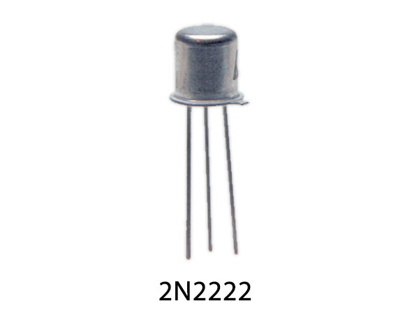
| 1 | Transistor | 2N2222A | 1 |
| 2 | Resistors | 10KΩ,57KΩ, 6.8KΩ, 1.5KΩ, 8.2KΩ | 3,1,1,1,1 |
| 3 | Ceramic Capacitor | 1nF, 0.1μF | 3, 1 |
| 4 | Electrolyte Capacitor | 0.1μF | 1 |
| 5 | Connecting Wires | – | |
| 6 | Battery | 9V | 1 |
2N2222A Pinout
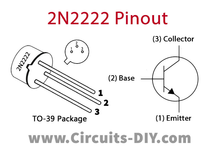
For a detailed description of pinout, dimension features, and specifications download the datasheet of 2N2222A
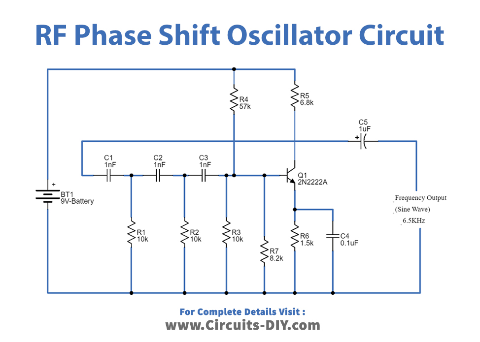
RC Phase Shift Oscillator Circuit
Working Explanation
As we can see Transistor 2N2222A is biased as a Common emitter (CE) single-stage amplifier and at the feedback, the RC network is formed by the same value capacitors and Resistors. Here the collector resistor RC limits the collector current of the transistor, resistors R4 and R3 form the voltage divider network while the emitter resistor R6 improves the stability. Next, the capacitors C5 and C4 are the emitter by-pass capacitor and the output DC decoupling capacitor, respectively. Further, the circuit also shows three RC networks employed in the feedback path. This whole RC phase shift oscillator circuit is powered by a 9V battery.
When we apply the power supply to this circuit, the random variations of base current caused by noise variations in the transistor and voltage variations in the power source produce oscillation, and these variations are amplified by the transistor amplifier. The arrangement causes the output waveform to shift by 180o during its course of travel from the output terminal to the base of the transistor. This RC phase shift oscillator feedback network is consisting of three stages of RC networks and these are identical and have equal values. Here each RC combinations provides 60º phase shift to the signal (RC1 + RC2 + RC3) that is (60 + 60 + 60) total feedback section provides 180º phase shift. The amplifier stage provides amplification with a 180º phase shift. Hence the total phase shift is 360º, and it provides positive feedback hence continuous undamped Oscillation is produced.
We can obtain continuous sine wave output with a fixed frequency. RC phase shift oscillator circuit will provide stable low-frequency oscillation. RC phase-shift oscillators can be designed in many ways as the number of RC networks in them is not fixed. However, it is to be noted that, although an increase in the number of stages increases the frequency stability of the circuit, it also adversely affects the output frequency of the oscillator due to the loading effect.
RC Phase Shift Oscillator Output Frequency Formula
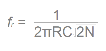
fr = Output frequency in Hertz
R = Resistance in ohms (R= R1 = R2 = R3)
C = Capacitance in Farads (C = C1 = C2 = C3)
N = Number of RC stages (Here N = 3)
Applications
Phase-shift oscillators are often used at the audio frequency as audio oscillators.
Related posts:
fisheranciverivens.blogspot.com
Source: https://www.circuits-diy.com/rc-phase-shift-oscillator-circuit/
0 Response to "Rc Circuit With Continuous Input Signal"
Postar um comentário